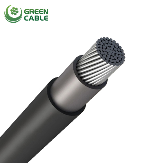
The AS/NZS 3675 standard specifies that covered conductors must have insulation material but no conductor or insulation screens. These conductors are used similarly to open wire 11 to 33kV bare overhead systems.
Conductors: Available in aluminium, aluminium alloy, and aluminium clad steel.
Water Blocking: Utilizes a special material that meets the test requirements of AS/NZS 3675.
Covering: These conductors are covered with a track-resistant UV-stabilised XLPE or with an inner layer of non-UV-stabilised XLPE and an outer layer of UV-stabilised High-Density Polyethylene (HDPE). If the latter is used, the average thickness of HDPE is not more than 40% of the specified minimum average thickness and not less than 1.0mm.
AS/NZS 3675
| Conductor size No./mm | Conductor d.c. resistance at 20°C | Conductor a.c. resistance at 80°C | Reactance at 50 Hz (460 mm spacing) | Continuous current carrying capacity | Fault current rating kA for 1 sec.* | Everday working tensionf kN | Maximum working tension (50% MBL) kN | Minimum breaking load kN | Minimum bending radius mm | |||||
| Based on 30°C ambient | Based on 40°C ambient | |||||||||||||
| Ω/km | Ω/km | Ω/km | Still air | 1.0 m/s wind | 2.0 m/s wind | |||||||||
| Alloy 6201 | ||||||||||||||
| 7/2.75 | 0.799 | 0.988 | 0.331 | 125 | 210 | 235 | 110 | 185 | 210 | 3.5 | 1.51 | 5.8 | 11.6 | 200 |
| 7/3.75 | 0.43 | 0.532 | 0.312 | 180 | 300 | 345 | 160 | 270 | 310 | 6.4 | 2.82 | 10.9 | 21.7 | 245 |
| 7/4.75 | 0.268 | 0.331 | 0.297 | 245 | 410 | 465 | 220 | 365 | 415 | 10.3 | 4.52 | 17.4 | 34.8 | 290 |
| 19/3.50 | 0.183 | 0.227 | 0.281 | 315 | 515 | 595 | 280 | 460 | 530 | 15.2 | 6.67 | 25.7 | 51.3 | 340 |
| Alloy 1120 | ||||||||||||||
| 7/2.75 | 0.713 | 0.881 | 0.331 | 130 | 220 | 250 | 115 | 195 | 225 | 3.7 | 1.49 | 4.96 | 9.91 | 200 |
| 7/3.75 | 0.383 | 0.474 | 0.312 | 190 | 320 | 365 | 170 | 285 | 325 | 6.8 | 2.64 | 8.8 | 17.6 | 245 |
| 7/4.75 | 0.239 | 0.296 | 0.297 | 260 | 430 | 485 | 230 | 385 | 435 | 11 | 4.07 | 13.6 | 27.1 | 290 |
| 19/3.50 | 0.163 | 0.202 | 0.281 | 330 | 545 | 625 | 295 | 485 | 560 | 16.2 | 6.26 | 20.9 | 41.7 | 340 |
| Conductor size No./mm | Conductor d.c. resistance at 20°C | Conductor a.c. resistance at 80°C | Reactance at 50 Hz (460 mm spacing) | Continuous current carrying capacity | Fault current rating kA for 1 sec.* | Everday working tensionf kN | Maximum working tension (50% MBL) kN | Minimum breaking load kN | Minimum bending radius mm | |||||
| Based on 30°C ambient | Based on 40°C ambient | |||||||||||||
| Ω/km | Ω/km | Ω/km | Still air | 1.0 m/s wind | 2.0 m/s wind | |||||||||
| 11 kv covered conductor Alloy 6201 | ||||||||||||||
| 7/3.75 | 0.43 | 0.532 | 0.312 | 185 | 295 | 330 | 165 | 265 | 295 | 6.4 | 2.82 | 10.9 | 21.7 | 285 |
| 7/4.75 | 0.268 | 0.331 | 0.297 | 245 | 390 | 440 | 220 | 350 | 395 | 10.3 | 4.52 | 17.4 | 34.8 | 330 |
| 19/3.50 | 0.183 | 0.227 | 0.281 | 315 | 500 | 560 | 280 | 445 | 500 | 15.2 | 6.67 | 25.7 | 51.3 | 380 |
| 22 kV covered conductor Alloy 6201 | ||||||||||||||
| 7/3.75 | 0.43 | 0.532 | 0.312 | 185 | 285 | 315 | 165 | 255 | 280 | 6.4 | 2.82 | 10.9 | 21.7 | 350 |
| 7/4.75 | 0.268 | 0.331 | 0.297 | 245 | 375 | 420 | 220 | 335 | 375 | 10.3 | 4.52 | 17.4 | 34.8 | 395 |
| 19/3.50 | 0.183 | 0.227 | 0.281 | 315 | 475 | 530 | 280 | 425 | 475 | 15.2 | 6.67 | 25.7 | 51.3 | 445 |
| 33kv covered conductor Alloy 6201 | ||||||||||||||
| 7/3.75 | 0.43 | 0.532 | 0.312 | 185 | 270 | 295 | 165 | 240 | 265 | 6.4 | 2.82 | 10.9 | 21.7 | 425 |
| 7/4.75 | 0.268 | 0.331 | 0.297 | 245 | 360 | 400 | 220 | 320 | 355 | 10.3 | 4.52 | 17.4 | 34.8 | 470 |
| 19/3.50 | 0.183 | 0.227 | 0.281 | 315 | 455 | 505 | 280 | 405 | 450 | 15.2 | 6.67 | 25.7 | 51.3 | 520 |
| Conductor size No./mm | Conductor d.c. resistance at 20°C | Conductor a.c. resistance at 80°C | Reactance at 50 Hz (460 mm spacing) | Continuous current carrying capacity | Fault current rating kA for 1 sec.* | Everday working tensionf kN | Maximum working tension (50% MBL) kN | Minimum breaking load kN | Minimum bending radius mm | |||||
| Based on 30°C ambient | Based on 40°C ambient | |||||||||||||
| Ω/km | Ω/km | Ω/km | Still air | 1.0 m/s wind | 2.0 m/s wind | |||||||||
| 11kv covered conductor Alloy 1120 | ||||||||||||||
| 7/2.75 | 0.713 | 0.881 | 0.331 | 130 | 215 | 240 | 115 | 190 | 215 | 3.7 | 1.49 | 4.96 | 9.9 | 230 |
| 7/3.75 | 0.383 | 0.474 | 0.312 | 190 | 315 | 345 | 170 | 280 | 310 | 6.8 | 2.64 | 8.8 | 17.6 | 285 |
| 7/4.75 | 0.239 | 0.296 | 0.297 | 26() | 415 | 470 | 230 | 370 | 420 | 11 | 4.07 | 13.6 | 27.1 | 330 |
| 19/3.50 | 0.163 | 0.202 | 0.281 | 330 | 525 | 595 | 295 | 470 | 530 | 16.2 | 6.26 | 20.9 | 41.7 | 380 |
| 22 kV covered conductor Alloy 1120 | ||||||||||||||
| 7/2.75 | 0.713 | 0.881 | 0.331 | 135 | 205 | 225 | 120 | 185 | 200 | 3.7 | 1.49 | 4.96 | 9.9 | 300 |
| 7/3.75 | 0.383 | 0.474 | 0.312 | 190 | 295 | 330 | 170 | 265 | 295 | 6.8 | 2.64 | 8.8 | 17.6 | 350 |
| 7/4.75 | 0.239 | 0.296 | 0.297 | 260 | 400 | 440 | 230 | 355 | 395 | 11 | 4.07 | 13.6 | 27.1 | 395 |
| 19/3.50 | 0.163 | 0.202 | 0.281 | 330 | 505 | 560 | 295 | 450 | 500 | 16.2 | 6.26 | 20.9 | 41.7 | 445 |
| 33kv covered conductor Alloy 1120 | ||||||||||||||
| 7/2.75 | 0.713 | 0.881 | 0.331 | 135 | 195 | 215 | 120 | 175 | 190 | 3.7 | 1.49 | 4.96 | 9.9 | 385 |
| 7/3.75 | 0.383 | 0.474 | 0.312 | 195 | 285 | 315 | 175 | 255 | 280 | 6.8 | 2.64 | 8.8 | 17.6 | 425 |
| 7/4.75 | 0.239 | 0.296 | 0.297 | 260 | 380 | 420 | 230 | 340 | 375 | 11 | 4.07 | 13.6 | 27.1 | 470 |
| 19/3.50 | 0.163 | 0.202 | 0.281 | 330 | 480 | 530 | 295 | 430 | 475 | 16.2 | 6.26 | 20.9 | 41.7 | 520 |
Please Feel free to give your inquiry in the form below.we will reply you in 24 hours.


